
SAYTAR-70
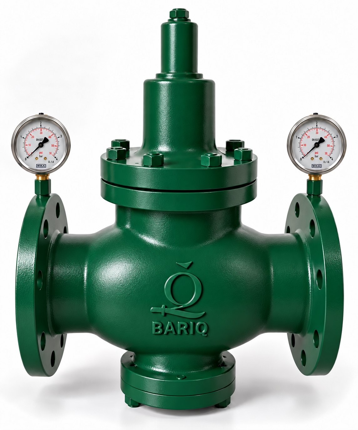
SAYTAR-70 Piston Pressure Reducing Valve
Sizes: DN50–DN200Pressure class: PN16Adjustment: 1.5–6 bar; optional 2–8 / 4–12 barTemperature: 0 to 40 °CMedia: Water and compressed airConnections: Flanged, EN 1092-2DOWNLOAD DATA SHEETRequest a Quote →
Built for dependable
flow control.
SAYTAR-70 — Piston Pressure Reducing ValveThe BARIQ SAYTAR-70 is an automatic piston-operated pressure reducing valve designed to reduce and stabilize downstream pressure to a preset value in water distribution pipework. Its epoxy-coated ductile-iron body is suitable for indoor and outdoor systems, with large internal passages designed to limit…
Know every critical detail.
Materials and construction details presented clearly for technical review.
Select a size.
See only what matters.
Choose the nominal size to display its dimensional data.
All values are in millimetres. Refer to the latest approved datasheet before final selection.
Everything your project needs.
SAYTAR-70 — Piston Pressure Reducing Valve
The BARIQ SAYTAR-70 is an automatic piston-operated pressure reducing valve designed to reduce and stabilize downstream pressure to a preset value in water distribution pipework. Its epoxy-coated ductile-iron body is suitable for indoor and outdoor systems, with large internal passages designed to limit flow resistance, vibration and pressure loss.
Technical Specifications
| Parameter | Specification |
|---|---|
| Size range | DN50–DN200 |
| Pressure class | PN16; PN25 and PN40 available on request |
| Standard adjustment range | 1.5–6 bar |
| Optional adjustment ranges | 2–8 bar / 4–12 bar |
| Working temperature | 0 to 40 °C |
| Compatible media | Water and compressed air |
| Flange connections | EN 1092-2 / ISO 7005-2 |
| Gauge connections | Optional Rp 1/4 in |
Material Specification
| Component | Material |
|---|---|
| Body and bonnet | Epoxy-coated ductile iron |
| Piston DN50–DN100 | Brass |
| Piston DN125–DN200 | Galvanized steel |
| Adjustment spring | Painted spring steel |
| Seat | Bronze |
| Other components | Steel and brass |
| Seat gasket, O-rings and lip seals | NBR rubber |
Dimensions
All dimensions in millimetres.
| DN | D | L | H | H1 max |
|---|---|---|---|---|
| 50 | 165 | 230 | 82 | 300 |
| 65 | 185 | 290 | 90 | 350 |
| 80 | 200 | 310 | 100 | 390 |
| 100 | 220 | 350 | 121 | 440 |
| 125 | 250 | 400 | 152 | 560 |
| 150 | 285 | 450 | 169 | 670 |
| 200 | 340 | 550 | 234 | 1050 |
D: flange outside diameter. L: face-to-face length. H: centreline to base. H1: maximum overall height.
Typical Applications
- Water distribution and irrigation
- Buildings and civil plants
- Cooling systems
See the product datasheet for pressure-loss and flow-capacity curves.